ESP8266
The ESP8266 is a WiFi-enabled SOC (system on chip) which can run open-source firmware, such as nodeMCU (an eLua interpreter), Ai-Thinker (a simple TCP/IP stack to act as a serial-to-TCP WiFi adapter), a bootloader to use with the ArduinoIDE or any other program written with the SDK (software development kit).
The ESP8266 chip can be readily purchased, presoldered on a small PCB module with different pins broken out for easy access.
Modules
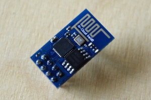
E-01
The E-01 module is of the cheapest and simplest modules with only 8 pins broken out to a 2x4 pin header. Since this module is not very breadboard friendly with the 8x2 pin header, we have a special E-01 USB flashing tool at the commons|lab.
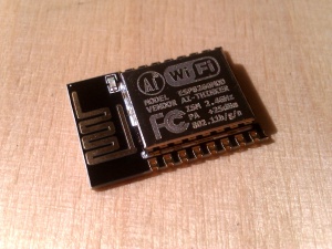
E-12
This module is FCC-licensed and has more pins of the ESP8266 broken out. The spacing if the pins is not the usual DIP/breadboard spacing of 0.1 inch. The small SMD on-board LED is connected to GPIO2 (Arduino pin 2) and is LOW-active.
E-12F
This version of the E-12 module has an improved PCB antenna design.
USB-Enabled boards
Amica
The NodeMCU Amica board has the E-12 module and a micro USB port on board.
Witty Cloud / Gizwits
Some modules consist of two small square PCBs which snap together with two 8-pin headers. The lower PCB hosts the USB UART adapter and two push buttons for "flash" and "reset", while the upper board hosts an ESP-12 module, an RGB LED on GPIO pins 15 (red), 12 (green) and 13 (blue) as well as a photo-resistor connected to the analog input (Arduino pin A0) and a user button on GPIO pin 4. The user button has inverted logic: The input is LOW when the button is pressed and HIGH when released.
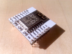
E-12 Break-out Adapter
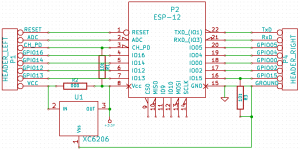
The the upper PCB can be replaced by a simple ESP-12 adapter board, which hosts a few pull-up / pull-down resistors and can be upgraded with a 3.3V voltage regulator, SMD-mounted on the bottom of the PCB. The zero-Ω resistor needs to be removed when upgraded with a 3.3V voltage regulator. This module can later be easily plugged into a project. This reduces the cost for the final project, while keeping the programming and prototyping easy. Additionally, this simplified board extends the battery life, because the USB UART is not part of the final project and thus consumes no power.
Flashing with Arduino IDE
The ESP2866 boards can be flashed with the Arduino IDE after installing the ESP boards into your Arduino IDE using the Board Manager by adding [the link] which is given at the Arduino core for ESP code repository.
- Choose 'Generic ESP8266 module' as 'Board' from the 'Tools' menu. (That seems to give good results with the E-01 USB flashing tool.)
- Make sure the ESP8266 has entered the bootloader.
- Press the upload button on the Arduino IDE.


