Difference between revisions of "Temperature monitoring with Dallas DS18B20 sensors and Domoticz"
(re-added wikimedia commons images + mention coating) |
(→Sensor Pinouts: Add ADC and I2C pins) |
||
| Line 17: | Line 17: | ||
| [[File:Wire white orange stripe.svg|60px|Pair 2 Tip]]<br/> White/orange stripe | | [[File:Wire white orange stripe.svg|60px|Pair 2 Tip]]<br/> White/orange stripe | ||
| Rx + || | | Rx + || | ||
| − | | | + | | NC (I2C SCL) |
| | | | ||
|- | |- | ||
| Line 23: | Line 23: | ||
| [[File:Wire orange.svg|60px|Pair 2 Ring]]<br/> Orange solid | | [[File:Wire orange.svg|60px|Pair 2 Ring]]<br/> Orange solid | ||
| Rx − || | | Rx − || | ||
| − | | | + | | NC (Analog) |
| | | | ||
|- | |- | ||
| Line 29: | Line 29: | ||
| [[File:Wire white green stripe.svg|60px|Pair 3 Tip]]<br/> White/green stripe | | [[File:Wire white green stripe.svg|60px|Pair 3 Tip]]<br/> White/green stripe | ||
| Tx + || | | Tx + || | ||
| − | | DATA | + | | DATA (I2C SDA) |
| [[File:Wire white.svg|60px]]<br/> White | | [[File:Wire white.svg|60px]]<br/> White | ||
|- | |- | ||
Latest revision as of 15:03, 11 October 2018
Sensors
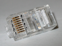
We use the DS18B20 sensors, pre-mounted into a waterproof flange from the BrewPi project. These have RJ11 (6P4C) connectors pre-crimped, which we replace with the more common RJ45 (8P8C) connectors and extend the cable with a standard CAT5e FTP (or STP) cable. The connections are similar to the the common T568B color coding and the follow the 802.3af (Power Over Ethernet / POE) with respect to the DC +/- colors.
Sensor Pinouts
Development Progress
Part 1: Fixed installation - 8 temperature sensors per ESP
In this part, we want to attach as many DS18B20 on one ESP as possible, with the circumstance, that the sensors are up to 40 meters apart from each other.
GPIO pin assignement
The NodeMCU has it's own designation of pins for the ESP8266, just like the Arduino has for the ATmega328.
We use D0 - D7 as digital inputs for the 1-Wire connection to the DS18B20 temperature sensors. D8 can not be used for 1-Wire devices, because the 1-Wire bus needs a pull-up resistor and the D8 is GPIO15 on the ESP8266, which needs to be LOW at power-on or reset, otherwise the controller will not boot.
Cable length testing
The first sensor with 20 meters CAT5e FTP (unshielded) cable and 8p8c (RJ54) connector and socket (for PCB) works, when connected to ESPeasy.
Production
The PCB was produced in the CNC. The parts were hand-soldered and covered with conformal coating (4 layers of acrylic spray). The PCB was installed in an outdoor rain-proof enclosure, together with a 5V/1A USB power supply.
Part 2: Valve control - 4 Sensors and 4 Relays per ESP
In this part, we need to monitor 4 temperatures and control two valves, which are operated with an electric motor. Each motor is operated by 220V and has an internal end-stop switch, which breaks the circuit at the correct motor/valve position, as well as returns the 220V on a feed-back contact to signal successful operation.
220V circuit
The electric motors can also be energized by manual override buttons, one to open and one to close each valve. The automatic control is done by one SSR (Solid State Relay), which is used for the state of the motor (ACTIVE/INACTIVE) and one electromechanical relay, which is used for the direction (OPEN/CLOSE).


