Difference between revisions of "Scratch for Arduino Workshop - 1.5h"
| (6 intermediate revisions by the same user not shown) | |||
| Line 35: | Line 35: | ||
==Exercise 1: Blink== | ==Exercise 1: Blink== | ||
===Building the circuit=== | ===Building the circuit=== | ||
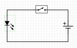
| − | [[File:Blink Schematic.png|thumbnail| | + | [[File:Blink Schematic.png|thumbnail|none|Schematic for Blink exercise]] |
| − | [[File:Blink Fritzing Schematic.png|thumbnail| | + | [[File:Blink Fritzing Schematic.png|thumbnail|none|Fritzing Arduino Blink Schematic]] |
===Building the logic=== | ===Building the logic=== | ||
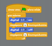
| + | [[File:Blink noVar el.png|thumbnail|none|Scratch for Arduino blocks for blink - Greek]] | ||
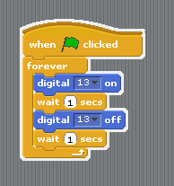
| + | [[File:Blink noVar en.png|thumbnail|none|Scratch for Arduino blocks for blink - English]] | ||
| + | ====Adding a variable==== | ||
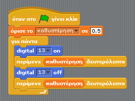
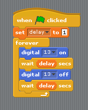
| + | [[File:Scratch blink+delay BlocksOnly.png|thumbnail|none|Scratch for Arduino blocks for blink with variable - Greek]] | ||
| + | [[File:Scratch blink+delay BlocksOnly en.png|thumbnail|none|Scratch for Arduino blocks for blink with variable - English]] | ||
| − | ==Exercise 2: | + | ==Exercise 2: LED with button== |
'''NOTE:''' Doing this exercise may require expanding the workshop to 2 hours depending on the previous experience of the pupils with Scratch or Arduino. If both subjects are presented for the first time it is recommended to skip this in the 1.5h format. | '''NOTE:''' Doing this exercise may require expanding the workshop to 2 hours depending on the previous experience of the pupils with Scratch or Arduino. If both subjects are presented for the first time it is recommended to skip this in the 1.5h format. | ||
| + | ===Building the circuit=== | ||
| + | [[File:LED+Button Fritzing Schematic.png|thumbnail|none|Schematic for LED with button circuit]] | ||
| + | |||
| + | ===Building the logic=== | ||
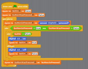
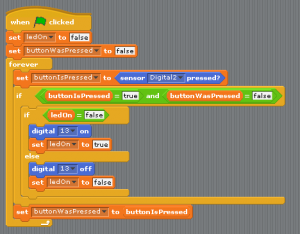
| + | [[File:Scratch_button_el.png|thumbnail|none|Scratch for Arduino blocks for LED with button - Greek]] | ||
| + | [[File:Scratch_button_en.png|thumbnail|none|Scratch for Arduino blocks for LED with button - English]] | ||
| + | |||
| + | Each time the button is pressed, we want to save the new button state and change the LED state. | ||
| + | |||
==Exercise 3: Theremin== | ==Exercise 3: Theremin== | ||
| + | ===Building the circuit=== | ||
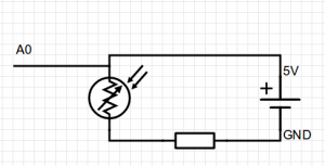
| + | [[File:Theremin Schematic.png|thumbnail|none|Simplified schematic for Light sensor (photoresistor)]] | ||
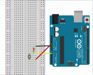
| + | [[File:Theremin Fritzing Schematic.png|thumbnail|none|Schematic for breadboard wiring for theremin]] | ||
| + | ===Building the logic=== | ||
| + | [[File:Scratch theremin BlocksOnly.png|thumbnail|none|Scratch for Arduino blocks for theremin - Greek]] | ||
| + | [[File:Scratch theremin BlocksOnly en.png|thumbnail|none|Scratch for Arduino blocks for theremin - English]] | ||
| + | |||
| + | We want to set the minimum and maximum notes to be played (48 & 72). Then we want to check what are the maximum and minimum values that we get from the light sensor. This we can see on Scratch for Arduino while the Arduino is connectedto read the value of ''Analog 0''. The maximum is the value shown with no shadow over the photoresistor and the minimum is when we cover the top of the photoresistor with our finger so not allowing any light on it. | ||
| + | Taken those four values we subtract the mins from the max and divide the two. This we call the ''ratio''. | ||
| + | Then we read the value of the sensor divide it by the ratio and add to it the minimum note. Set this to another variable ''note'' and play that! | ||
| + | |||
| + | We can experiment by changing the min max notes if we want to player higher or lower notes. Change the instrument and change the number of beats in order to hear the changes of the notes faster or slower. | ||
Latest revision as of 11:47, 28 March 2017
This workshop is designed for secondary education pupils with the goal to introduce them to the world of physical computing by using visual programming. The workshop uses for these purposes the Arduino UNO and some simple electronic components programming it with Scratch for Arduino (S4A).
Setting Up
It is recommended to have a PC/Laptop and Arduino UNO plus the components for every 3-4 pupils. Equipment:
- Laptop or PC workstation with speakers
- Pre-installed Arduino IDE and S4A.
- Arduino UNO
- USB Cable type B
- Breadboard
- 5 male to male jumper wires
- Photoresistor
- 10kOhm resistor
- LED 5V
Introduction
What is Arduino?
Arduino is an open-source electronics platform based on easy-to-use hardware and software. It is possible to read inputs from the physical or digital world, a light sensor, a button or a tweet, and translate it to an output, lighting a LED, moving a motor or sending an email. The electronics board is using pins where jumper wires can be easily connected to form electronic circuits with the use of breadboards. The board can be programmed using the Arduino IDE with a simplified version of C++ or with visual programming by using Scratch for Arduino.
Scratch for Arduino
S4A is a Scratch modification that allows for simple programming of the Arduino open source hardware platform. It provides new blocks for managing sensors and actuators connected to Arduino. There is also a sensors report board similar to the PicoBoard one.
Using the breadboard
A breadboard is a construction base for prototyping of electronics. Because the solderless breadboard does not require soldering, it is reusable. This makes it easy to use for creating temporary prototypes and experimenting with circuit design. For this reason, solderless breadboards are also extremely popular with students and in technological education.
More information on how to use a breadboard
Exercise 1: Blink
Building the circuit
Building the logic
Adding a variable
Exercise 2: LED with button
NOTE: Doing this exercise may require expanding the workshop to 2 hours depending on the previous experience of the pupils with Scratch or Arduino. If both subjects are presented for the first time it is recommended to skip this in the 1.5h format.
Building the circuit
Building the logic
Each time the button is pressed, we want to save the new button state and change the LED state.
Exercise 3: Theremin
Building the circuit
Building the logic
We want to set the minimum and maximum notes to be played (48 & 72). Then we want to check what are the maximum and minimum values that we get from the light sensor. This we can see on Scratch for Arduino while the Arduino is connectedto read the value of Analog 0. The maximum is the value shown with no shadow over the photoresistor and the minimum is when we cover the top of the photoresistor with our finger so not allowing any light on it. Taken those four values we subtract the mins from the max and divide the two. This we call the ratio. Then we read the value of the sensor divide it by the ratio and add to it the minimum note. Set this to another variable note and play that!
We can experiment by changing the min max notes if we want to player higher or lower notes. Change the instrument and change the number of beats in order to hear the changes of the notes faster or slower.
